Addressable Fire Alarm Panels
Shield ADDRESSABLE ZFP NETWORKABLE FIRE PANELS
Shield·SKU: SHIELD-F-7124
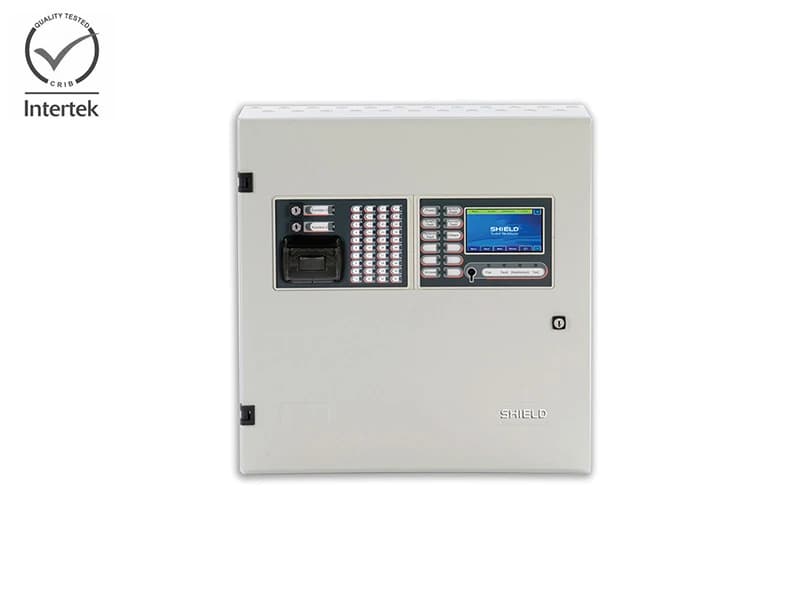
ZFP is a powerful, intuitive and feature-rich range of 1 to 8 loop addressable fire panels from Shield.
Request a quoteDescription
ZFP is a powerful, intuitive and feature-rich range of 1 to 8 loop addressable fire panels from Shield.
Features
- Third-party certified to EN54 parts 2 and 4 by Intertek
- Communication protocol – Shield XP95/Discovery
- Full compatibility with the Shield range of fire detectors, call points, sounders, beacons and control modules.
- Three cabinet sizes – standard (1, 2 or 4 loops), medium (2, 4, 6 or 8 loops) and large (2, 4, 6 or 8 loops)
- Full colour LCD touchscreen with an intuitive interface & digital QWERTY keyboard (touchscreen can be fully customized with a company logo)
- Secure fault tolerant network (needs separate network driver PCB)
- Up to 128 peers to peer node capacity (64 panels plus up to 64 Compact Controllers/Repeaters
- Very flexible cause and effects
- Wide range of Switch & Indicator modules c/w slide-in labels for straightforward customization. (Common word processor templates available online)
- Multiple “A-Bus” peripherals (I/O Units, Relays, Sounder Extender Cards, Conventional Zone Cards, etc.)
- Programmable via galvanically isolated USB port
- Up to 200 separate zonal LEDs per panel (100 on standard sized cabinets)
- 10,000 programmable and indicatable detection zones
- Up to 38 characters of custom text per loop device
- Wide range of supported languages
- Emailable firmware updates (no flash programmer required!)
- 20,000+ event memory (filterable by fire, fault and date)
- Automatic daylight saving (BST/GMT)
- 4 programmable operational modes
- Optional thermal printer with front-loading paper
- PC logging option for end-user
- 4 GB Micro SD memory simplifies off-site configuration
- Well-designed metal cabinets aid installation
- 20-way heavy duty brass earth bar(s) as standard
- 72-hour standby (plus 30 min alarm) in standard cabinets
- Powerful engineering and commissioning functions including ‘Safe Mode’, ‘Device Manager’ and more
- Powerful and intuitive PC programming tools
- Optional graphical interface solutions
- Up to 18Ah batteries in standard cabinets, 38Ah in larger cabinets.
Specifications
TECHNICAL DATA| POWER SUPPLY & CHARGER | |
| Mains Supply Operating Voltage | 230Vac ±10% 50/60Hz 810mA max. |
| Rated current | 810mA Max (Standard cabinet QFNs; 1.35A Max (Medium & Large Cabinet QFNs) |
| Internal power supply | 5A (Standard cabinet QFNs); 5A (Medium & Large Cabinet) |
| Max. continuous output current (incl. charging) | 5A (Standard cabinet QFNs; 5A (Medium & Large Cabinet) |
| Max. VRLA battery size and type | 2 x 12V 18Ah (Standard cabinet QFNs); 2 x 12V 38Ah (Medium & Large Cabinet) |
| LOOP DRIVERS | |
| Number of loops | 1, 2, 4, 6 or 8 dependents on model |
| Max. output current per loop | 500mA (Voltage: 25V min; 34V max) |
| Communication Protocol | Shield XP95 (max. 127 addressable devices per loop) |
| Type of cable / Max. cable length per loop | Fire resistant screened, up to 2.5mm2 / 1.5KM max length |
| Max. allowable loopimpedance/capacitance | 20 ohms (each conductor) |
| Max. cable capacitance | .27uF |
| CONVENTIONAL SOUNDER CIRCUITS | |
| Number/type of conventional sounder | 2 x 1A outputs. Protected by resettable overload circuit 19.5V min; 28V max |
| Output voltage | 19.5V minimum, 28V maximum |
| Type of cable / Max. cable length per loop | Fire resistant screened, up to 2.5mm2 / 1.5KM max length |
| AUXILIARY INPUTS (PROGRAMMABLE) | |
| Number of auxiliary inputs | 2 (Connect to 0V to trigger, Max. input voltage 27Vdc non-latching). 6800 ohm, 5%Tol, 0.25W |
| EOL resistor value (supplied) | 6800-ohm, 5% tolerance, 0.25W |
| Trigger resistor (supplied) | 470R, 0.25W |
| RELAY OUTPUTS (PROGRAMMABLE) | |
| Number of relay outputs | 2 x programmable auxiliary relays; 1 x failsafe fault relay; 1 x 24Vdc aux. power output |
| Relay type & outputs | 1A, 30Vdc (maximum). Voltage free, single pole changeover |
| Fault relay | Active when faults are present or on total power failure |
| 24Vdc auxiliary power output | 19.5V minimum, 28V maximum. Max current 100mA. |
| INDICATORS AND CONTROLS | |
| Standard provision | All models include a Z41 Control module which comprises a full colour 4.3” touchscreenAll mandatory EN54 indicators, 3 spare LEDs & a key switch allowing access to AL2 |
| Zonal Indicators | Up to 200 programmable LEDs available via Switch & Indicator expansion modules |
| Switches & onboard printers | Multiple switch & printer configs available via Switch & Indicator expansion modules |
| Switch & Indicator module capacity | 2 (standard cabinets); 4 (medium cabinets); 6 (large cabinets). 1 x Z41 req. per panel |
| COMMUNICATION BUSES | |
| On-board Serial Printer (Optional) | 1 x RS232 connector |
| Pager/DECT Interface | 1 x RS232 connector |
| Networking | 1 x RS485 connector (hi-integrity fault-tolerant) |
| Peripheral Bus (A-Bus) | 1 x RS485 connector. Allows the connection of up to 15 A-Bus PCBs.Wiring requirements = 2 core plus screen plus 2 core for power. |
| PC Interface | Galvanically isolated USB connector (provided on the Z41 Control/Display module) |
| NETWORKING | |
| Network type | RS485(hi-integrity fault tolerant, ring wired). 1xQHN PCB required per networked panel |
| Maximum no. of network nodes | 128 (up to 64 x 8 loop panels and 64 x compact controllers) |
| Type of cable / Max. cable length | Fire resistant screened, up to 2.5mm2; 1KM between nodes; 128KM (max network length) |
| Network wiring | Fire resistant screened cable, up to 2.5mm2 |
| Detail | Events (Fires, Faults, Disablements, Tests) & Actions (Silence/Resound Sounders, Reset) can be accepted over the network. Zones, Input & Output Groups, etch can be shared over the network |
Catalogue family reference SHIELD-F-7124 identifies this manufacturer product page; it is not an orderable manufacturer SKU. Confirm the required model and configuration when requesting information.
Technical Specifications
| 24Vdc auxiliary power output | 19.5V minimum, 28V maximum. Max current 100mA. |
|---|---|
| Catalogue family reference | SHIELD-F-7124 |
| Communication Protocol | Shield XP95 (max. 127 addressable devices per loop) |
| Detail | Events (Fires, Faults, Disablements, Tests) & Actions (Silence/Resound Sounders, Reset) can be accepted over the network. Zones, Input & Output Groups, etch can be shared over the network |
| EOL resistor value (supplied) | 6800-ohm, 5% tolerance, 0.25W |
| Fault relay | Active when faults are present or on total power failure |
| Internal power supply | 5A (Standard cabinet QFNs); 5A (Medium & Large Cabinet) |
| Mains Supply Operating Voltage | 230Vac ±10% 50/60Hz 810mA max. |
| Max. allowable loopimpedance/capacitance | 20 ohms (each conductor) |
| Max. cable capacitance | .27uF |
| Max. continuous output current (incl. charging) | 5A (Standard cabinet QFNs; 5A (Medium & Large Cabinet) |
| Max. output current per loop | 500mA (Voltage: 25V min; 34V max) |
| Max. VRLA battery size and type | 2 x 12V 18Ah (Standard cabinet QFNs); 2 x 12V 38Ah (Medium & Large Cabinet) |
| Maximum no. of network nodes | 128 (up to 64 x 8 loop panels and 64 x compact controllers) |
| Network type | RS485(hi-integrity fault tolerant, ring wired). 1xQHN PCB required per networked panel |
| Network wiring | Fire resistant screened cable, up to 2.5mm2 |
| Networking | 1 x RS485 connector (hi-integrity fault-tolerant) |
| Number of auxiliary inputs | 2 (Connect to 0V to trigger, Max. input voltage 27Vdc non-latching). 6800 ohm, 5%Tol, 0.25W |
| Number of loops | 1, 2, 4, 6 or 8 dependents on model |
| Number of relay outputs | 2 x programmable auxiliary relays; 1 x failsafe fault relay; 1 x 24Vdc aux. power output |
| Number/type of conventional sounder | 2 x 1A outputs. Protected by resettable overload circuit 19.5V min; 28V max |
| On-board Serial Printer (Optional) | 1 x RS232 connector |
| Output voltage | 19.5V minimum, 28V maximum |
| Pager/DECT Interface | 1 x RS232 connector |
| PC Interface | Galvanically isolated USB connector (provided on the Z41 Control/Display module) |
| Peripheral Bus (A-Bus) | 1 x RS485 connector. Allows the connection of up to 15 A-Bus PCBs.Wiring requirements = 2 core plus screen plus 2 core for power. |
| Published manufacturer stated standards statement 1 | Third-party certified to EN54 parts 2 and 4 by Intertek |
| Rated current | 810mA Max (Standard cabinet QFNs; 1.35A Max (Medium & Large Cabinet QFNs) |
| Relay type & outputs | 1A, 30Vdc (maximum). Voltage free, single pole changeover |
| Standard provision | All models include a Z41 Control module which comprises a full colour 4.3” touchscreenAll mandatory EN54 indicators, 3 spare LEDs & a key switch allowing access to AL2 |
| Switch & Indicator module capacity | 2 (standard cabinets); 4 (medium cabinets); 6 (large cabinets). 1 x Z41 req. per panel |
| Switches & onboard printers | Multiple switch & printer configs available via Switch & Indicator expansion modules |
| Trigger resistor (supplied) | 470R, 0.25W |
| Type of cable / Max. cable length | Fire resistant screened, up to 2.5mm2; 1KM between nodes; 128KM (max network length) |
| Type of cable / Max. cable length per loop | Fire resistant screened, up to 2.5mm2 / 1.5KM max length |
| Zonal Indicators | Up to 200 programmable LEDs available via Switch & Indicator expansion modules |
Documents & Technical Downloads
Related Products
View Cataloguearrow_forward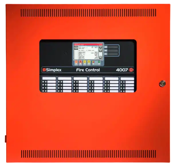
Simplex 4007-9201 (Fire Alarm Control Panel)
Indicative Price
from

Simplex 4010-9501 (4010Es Facp 240V)
Indicative Price
from
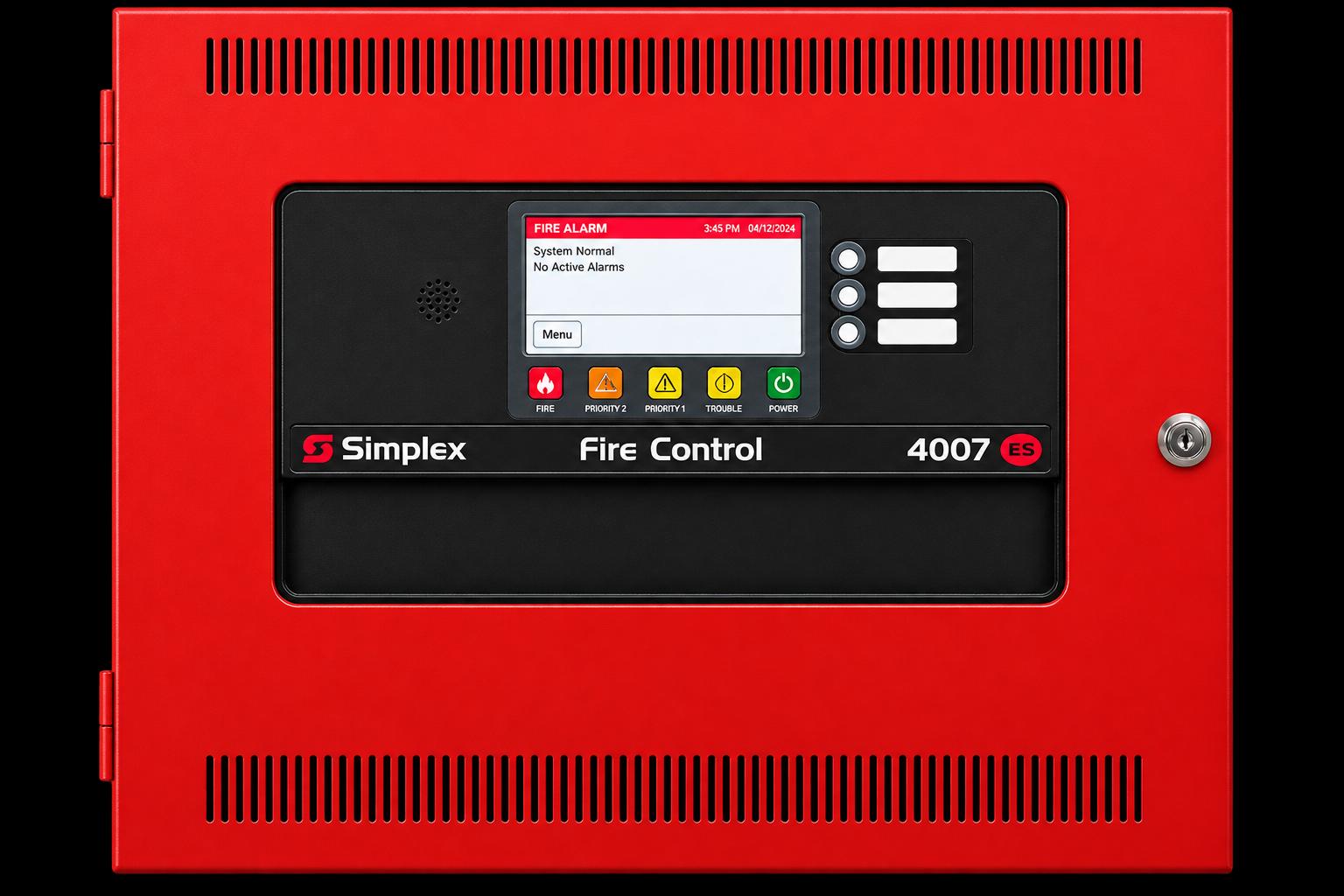
Simplex 4010-9502 (4010Es Facp 240V Red)
Indicative Price
from