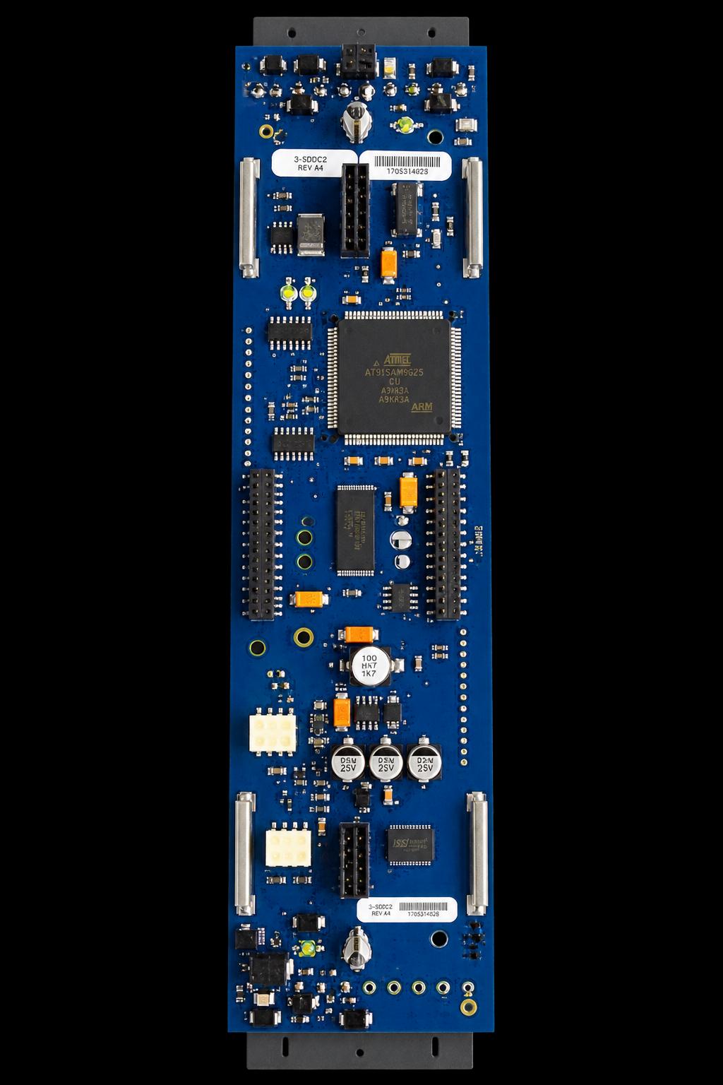
Edwards 3-SDDC2 (Signature Driver Controller Module)
Indicative Price
Excluding local taxes and shipping.
Signature Driver Controller Module that provides an intelligent interface between the 3-CPU3 module and Signature Series devices
Description
Edwards 3-SDDC2 — the Dual Signature Driver Controller, a local rail module that provides the intelligent interface between the CPU module and two full circuits of Signature Series devices.
The module carries its own microprocessor to coordinate, process and interpret information received from and sent to Signature devices, taking power and communications directly from the control panel rail assembly. It occupies one local rail module space and supports two Signature data circuits through two plug-in 3-SDC1 Signature Device Cards, which are included. Communication is fully digital, using a broadcast poll to check the entire circuit for changes of state and then a direct address search to locate the reporting devices, so only new information moves on the wire — this keeps the baud rate low and response fast, and is what makes the platform suitable for retrofit onto existing wiring.
The controller maps the circuit and commits it to non-volatile memory, recording the physical connection sequence including T-taps, then compares actual device data against the expected site-specific program and posts a map fault naming any device that does not match.
Specifications
| Installation | 1 LRM (local rail module) space |
| Module configuration | 2 addressable circuits (2 x 3-SDC1 cards) |
| Operating current | Standby 264 mA; alarm 336 mA (includes a full loop of Signature devices) |
| Operating voltage | 24 VDC nominal |
| Detectors supported | 125 per 3-SDC1 card |
| Modules supported | 125 module addresses per 3-SDC1 card |
| 2-wire smoke power output | 100 mA per 3-SDC1 card (not included in the operating current above) |
| Signature circuit voltage | 20 VDC ±5% |
| Max Signature circuit resistance | 100 ohms |
| Max Signature circuit capacitance | 0.5 µF |
| Circuit wiring styles | Class B, Class A or Class X |
| Communications format | 100% digital |
| Address requirements | Automatic |
| Termination | Removable plug-in terminal strips on the module |
| Permissible wire size | 18 to 12 AWG (0.75 to 2.5 mm²) |
| Operating environment | 32°F (0°C) to 120°F (49°C), 93% RH, non-condensing |
| Agency listings | UL, ULC, EN54, CE, FM |
| Ship weight | 0.5 lb (0.23 kg) |
Installation notes
- Cabinet and node limits: up to five 3-SDDC2s or ten 3-SSDC2s per node, with a maximum of 10 Signature circuits per cabinet. This ceiling, not the rail space, is usually what caps a design.
- The current figure already includes the loop: the data sheet notes that the 264 mA standby / 336 mA alarm current shown includes a full loop of Signature devices. The 100 mA per card of 2-wire smoke power output is the exception — it is not included and must be added.
- Loop distance depends on wire type, not just gauge: the data sheet gives separate distance charts for non-twisted non-shielded and twisted-pair non-shielded wire. For non-twisted non-shielded #14 AWG, detectors only reaches 14,752 ft (4,497 m), but a mixed 125 detectors plus 125 modules falls to 5,738 ft (1,749 m), and the same mix on #18 AWG to 2,271 ft (692 m). Adding 2-wire smokes reduces device counts further. Size the run from the chart matching the actual mix.
- CO detectors get advance warning: where a detector includes carbon monoxide detection, the panel automatically generates a unique CO maintenance signal roughly 6 months before the CO sensor reaches end of life, so replacement can be planned before an end-of-life trouble is posted.
- Dirty detector staging: at 80% of environmental compensation used the controller reports a maintenance alert or dirty condition naming the device; the detector keeps operating until compensation is exhausted, at which point a dirty trouble is posted.
- Survivability modes: if the CPU fails, the loop controller keeps polling and any alarm is sent on the local rail communication bus, producing a common alarm at the panel. If the driver controller itself fails, dedicated circuitry still makes the node aware of an alarm and the CPU communicates it to the network.
- Backward compatibility and upgrade path: the 3-SDDC2 is fully backward compatible with 3-SDDC and 3-SDDC1. Note a gap in the document: the upgrade text says to replace a 3-SSDC1/3-SDDC1 local rail module with a “3-SSDC2-MB” local rail module and reuse the existing 3-SDC1 device cards and filters, but no 3-SSDC2-MB appears anywhere in the sheet’s ordering information table. Confirm that part number with Edwards before quoting an upgrade.
- Filler plates are a separate order: 3-FP (or 4-FIL for EST4) must be ordered separately when no LED or LED/switch module is installed on the inner door.
- Conventional devices: refer to the FACU compatibility lists for compatible conventional detectors; do not assume a 2-wire device is supported.
Related models
- 3-SSDC2 — single-circuit version in the same one rail space, shipping with one 3-SDC1 card and expandable to two circuits. Standby 144 mA, alarm 204 mA.
- 3-SDC1 — the Signature Device Card itself, sold separately to upgrade a 3-SSDC2 to a 3-SDDC2.
- 3-SDDC2-E — EN54-compliant version of the dual driver controller, supplied with two 3-SDC1 device cards.
- 3-SDDC1 — the previous-generation dual driver controller that the 3-SDDC2 replaces and remains compatible with.
Specifications taken from the Edwards data sheet “Signature Driver Controller Modules — 3-SSDC2, 3-SDDC2, 3-SDC1,” document E85010-0130, Issue 2.0. Manufacturer specifications are subject to change without notice.
Supplier availability note: discontinued/legacy. Confirm availability before ordering.
Technical Specifications
| 2-wire smoke power output | 100 mA per 3-SDC1 card (not included in the operating current above) |
|---|---|
| Address requirements | Automatic |
| Agency listings | UL, ULC, EN54, CE, FM |
| Circuit wiring styles | Class B, Class A or Class X |
| Communications format | 100% digital |
| Detectors supported | 125 per 3-SDC1 card |
| Installation | 1 LRM (local rail module) space |
| Max Signature circuit capacitance | 0.5 µF |
| Max Signature circuit resistance | 100 ohms |
| Module configuration | 2 addressable circuits (2 x 3-SDC1 cards) |
| Modules supported | 125 module addresses per 3-SDC1 card |
| Operating current | Standby 264 mA; alarm 336 mA (includes a full loop of Signature devices) |
| Operating environment | 32°F (0°C) to 120°F (49°C), 93% RH, non-condensing |
| Operating voltage | 24 VDC nominal |
| Permissible wire size | 18 to 12 AWG (0.75 to 2.5 mm²) |
| Ship weight | 0.5 lb (0.23 kg) |
| Signature circuit voltage | 20 VDC ±5% |
| Termination | Removable plug-in terminal strips on the module |